


Want to eliminate unplanned downtime and extend the lifespan of your critical assets?
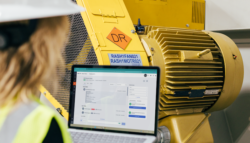
Contact us to see how our comprehensive, AI-driven predictive maintenance platform can optimize your operations.
View Case Study: Transforming Commercial Laundry Operations Through Predictive Maintenance 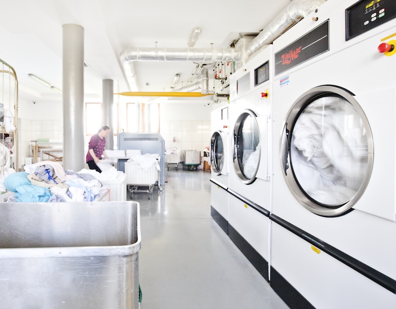
Transforming Commercial Laundry Operations Through Predictive Maintenance
TMC Laundry deployed KCF SMARTdiagnostics®, preventing 28 hours of downtime in 90 days while improving maintenance planning, labor efficiency, and reliability.