Which wireless vibration sensors can you trust?
January 17, 2025 | Machine Health Solutions
Overview
Wireless vibration sensors are an enabling technology driving the biggest improvements in asset health and reliability since the advent of route-based vibration monitoring. These sensors are one of the most important components of predictive maintenance programs because the data they generate is foundational to analytics, directing corrective maintenance tasks, and ultimately plant floor engagement with predictive maintenance. Excitement over this new opportunity has flooded the predictive maintenance market with inexperienced companies and poorly designed sensors, many of which are error-prone because they violate best practices in sensor design that have been established over the last six decades by the legacy piezoelectric accelerometer industry.
This problem can be hidden by clever analytics and the fact that error is often only seen when an asset has a fault condition that overlaps with the error characteristics of the sensor. For this reason, pilots rarely expose this problem, but over time (and when customers scale a solution), they will experience false positives and missed diagnoses. Identifying and avoiding sensors that are error-prone is a challenge because expensive test apparatuses are needed to quantify the error, and many wireless sensor companies simply ignore the accuracy of the overall sensor and instead claim the accuracy of the OEM accelerometer built into their wireless product. This misinformation and lack of information are undermining trust in online monitoring and slowing the trend toward continuous online asset health monitoring.
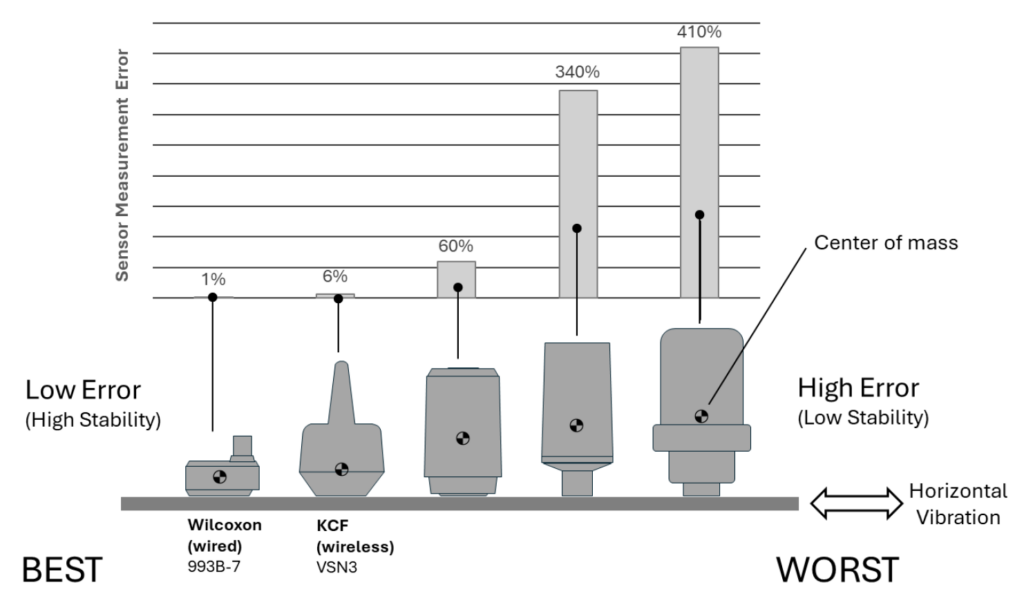
This paper addresses this problem by showing that several key physical sensor characteristics, which are easily observable by a non-expert, can be used to estimate the expected accuracy of a given sensor. The magnitude of this problem is significant because experimental testing shows that peak error in transverse (lateral to the sensor) vibration ranges from 60% to 410% for sensor designs commonly found in the predictive maintenance market. Ultimately, this paper encourages both wireless sensor providers and end customers alike to consider sensor designs that enable high accuracy measurement and ensure machine diagnostic accuracy.
Background
MEMs accelerometers, lithium batteries, low power wireless communications, and cloud computing have enabled a new era in asset management in which machines can be monitored continuously and at low cost. A wide range of balance of plant assets like pumps, fans, gearboxes, and motors can now be monitored in near real-time. The impact is high in terms of improved worker safety, lower downtime, and reduced maintenance cost.
This new market has sparked an in-rush of startup predictive maintenance sensor and software companies backed by Silicon Valley money. Many of these companies are proficient at building cloud software but lack a fundamental understanding of complex machine vibration and sensor mechanical design for accurate vibration measurement.
This deficiency is most evident in sensor designs. Sensors are a particularly important aspect of predictive maintenance solutions because they are the fundamental building block on which the analytics and all other predictive maintenance are based. A predictive maintenance product can offer the best analytics in the world, but if the data going into the analytics is inaccurate, the results will also be inaccurate.
For more than 60 years, experts in vibration measurement have refined accelerometer designs for accurate measurement over a wide frequency band. The resulting wired accelerometer products have a highly compact form factor and stable mount to the machine. In contrast, accelerometers with an unstable form factor (high center of mass and narrow base) like the ones built by many incumbent wireless predictive maintenance companies are simply out of step with the mature accelerometer market because they directly ignore the first principles of vibration sensor design.
Sensor Design and Accuracy
However challenging it is to design a wireless vibration sensor, it is not challenging to intuitively judge a sensor’s measurement accuracy by accounting for a few basic characteristics that strongly impact accuracy. This paper will explain how to go about that assessment without using specialty test equipment.
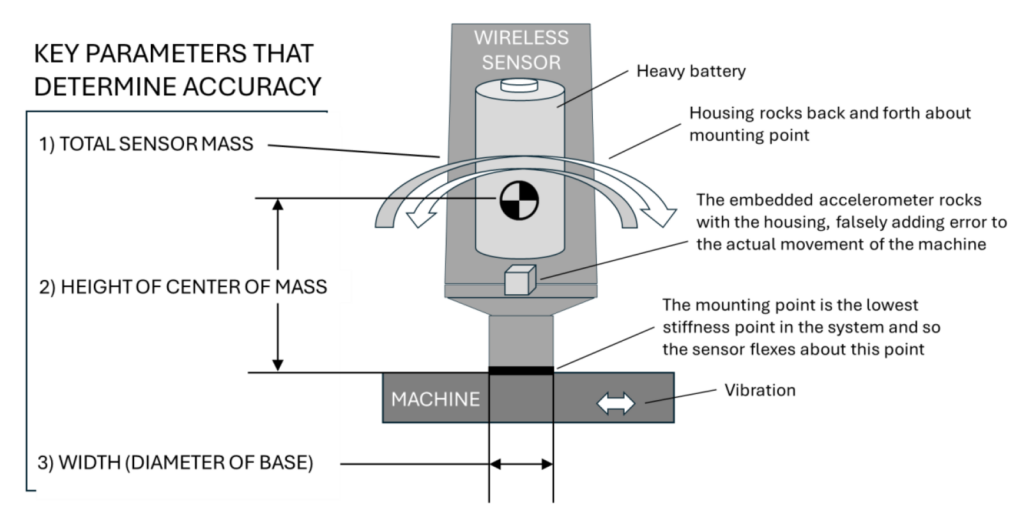
To understand what impacts accuracy, first consider a vibration sensor mounted at the inboard radial location on a typical 200 Hp industrial motor. If machine vibration were only perpendicular to the sensor mounting surface (i.e., only up-and-down, no side-to-side motion) and the center of mass of the sensor aligned with the mounting point (patented by KCF Technologies), most wireless sensors would perform reasonably well [1]. Unfortunately, vibration at a sensor monitoring point, on average, is often roughly equal in three dimensions (depending on the mounting location, equipment foundation, etc.). Most importantly, vibration parallel or tangential to the mounting surface (lateral or transverse to the sensor) causes the sensor to sway back and forth. This tendency to sway may seem inconsequential at first glance, but testing results show that it can be responsible for major errors and can result in missed or false diagnosis.
This paper shows that three key parameters can be used to express the expected amount of sway: 1) total sensor mass, 2) height of center of mass, and 3) width (diameter) of the base in contact with the machine. These parameters can then be used to estimate wireless vibration sensor error without thorough laboratory testing.
Representative Sensor Test Results
To show how these characteristics influence wireless sensor measurement accuracy, a test was completed in a precisely controlled laboratory environment. A representative sensor was built that replicates the height, weight, and mount of common wireless vibration sensors. An adjustable height mass was used to vary the height of the center of mass and cover a range of different sensor designs.
The representative sensor was stud-mounted on a shaker table with a torque of 12 N-m. A reference accelerometer was mounted on the shaker table. The mounting location of the accelerometer in the representative sensor was set as low as possible to offer a conservative estimate for error. In other words, the error could be much worse than shown in this analysis if the accelerometer is mounted higher in the product, which is likely the case for some of the wireless accelerometers on the market. Two identical 100mV/G Dytran model 3035BG accelerometers were used for the reference accelerometer and the accelerometer in the representative sensor.
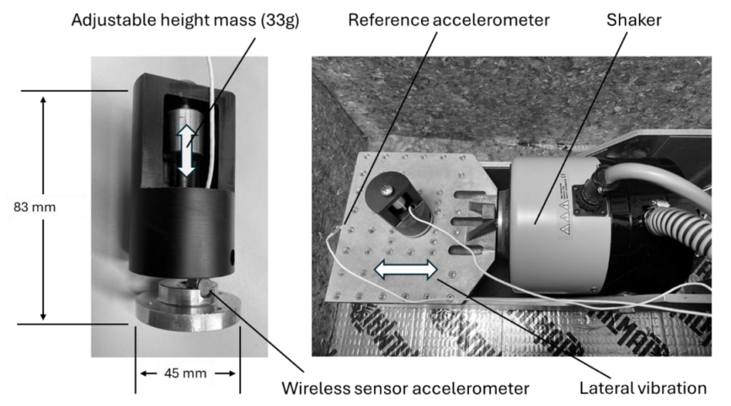
The shaker table vibrated the sensor horizontally or laterally to the mounting orientation of the sensor. Closed loop control was used to maintain the shaker amplitude precisely at 1G.
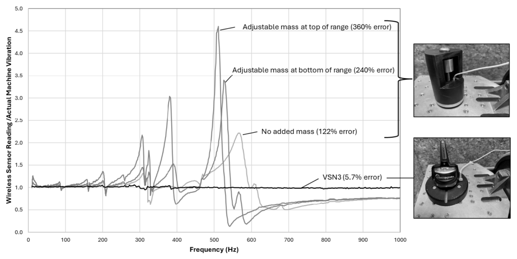
The ratio of the measured input acceleration (used for the shaker vibration control) relative to the acceleration measured in the representative sensor (known as transmissibility) was computed. The vibration varied from 10 Hz to 1000 Hz. The range was limited to 1000 Hz since it encompasses the range where high accuracy measurement is essential. Key fault frequencies that fall in that range include bearing, gear mesh, vane pass, belt, and coupling fault frequencies. There is value in measuring above 1000 Hz to observe electrical faults, cavitation, looseness, and lubrication issues, but high accuracy in that range is less important for characterizing faults.
Three different representative sensor configurations were tested and compared to the KCF VSN3. The first configuration includes the base and outer shell but no added mass. The second and third have a 33g mass (similar to the weight of a TL-4920 battery found in some wireless sensors) that can be adjusted vertically to increase or decrease the height of the sensor center of mass.
The frequency responses of each of these variants are shown in the plot below. A value of 1.0 means the acceleration measured in the representative sensor matches the movement of the shaker (or machine). A value of 0.5 means the representative sensor only reported half the amplitude level of the machine. A value of 2 means the sensor over-reported the vibration of the machine by a factor of 2.
KCF has minimized this problem by implementing a patented wireless solution called DARTwirelessTM that reduces power consumption by as much as 8X [2,3]. This allows the battery to be smaller, lighter, and located lower in the sensor housing.
Estimating Sensor Accuracy
Performing the experiment outlined above for a given wireless sensor is impractical for most manufacturers looking to buy a predictive maintenance solution because it requires expensive specialty equipment and aggregating and analyzing the data can be complicated. This paper simplifies the sensor assessment by relating the accuracy of the representative sensor to a simple metric that can be used by anyone. The metric is called the “Instability Index.” It is defined as the sensor’s total mass multiplied by the height of the center of mass (also known as the “first moment of area” in physics) divided by the base width. The width in this case is usually just the diameter of the contact patch between the sensor and the machine. The height of the center of mass can be estimated by laying the sensor horizontally on a pen and balancing the sensor. The distance between the balance point and the mounting surface corresponds to the center of mass height.

The sensor error for the three configurations, along with that of KCF’s VSN3, are shown in the table below. The Instability Index is calculated based on the three characteristic parameters of the four sensor variants. In this case, the units of measure matter. Length was measured in millimeters and mass in grams.

An industry benchmark for high stability is the Wilcoxon 993B-7 sensor. It is included in the table as a gold standard for an ideal sensor design although it has neither a battery nor wireless components. KCF’s VSN3 sensor is a close second followed by several others with considerably lower stability.
[2] KCF Technologies, Channel adaptation in sensor networks, US Patent US9271170B1, 2016[3] KCF Technologies, Compression method for resource constrained local area networks, US Patent US10873791B1, 2020
In the plot below, the Instability Index is plotted versus the peak error measured in the lab test.
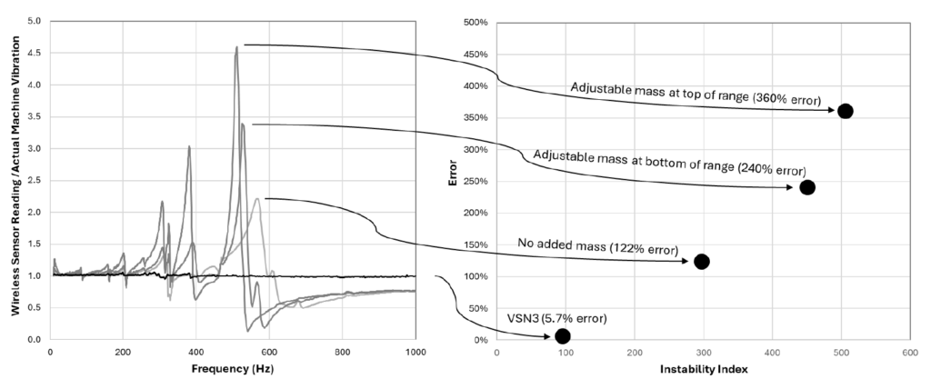
This paper shows that as the Instability Index increases with the sensor error. However, this relationship is not linear. There appears to be a point where errors become very small for a given Instability Index. This is likely because the natural frequencies of a sensor are outside the measurement range. This is the case for KCF’s VSN3.
Comparing Sensors in the Predictive Maintenance Market
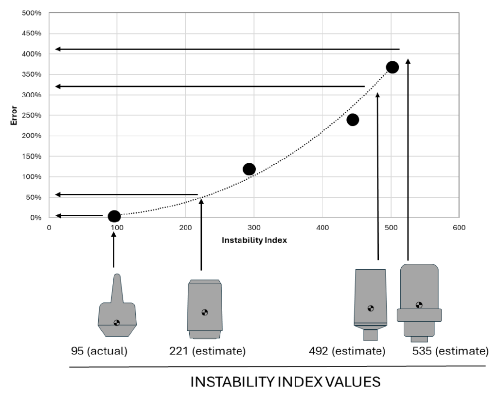
The above results can be used to estimate error for various other wireless sensors by calculating their Instability Index using information collected from sensor datasheets and intuition about where the center of mass lies. The Instability Index values can then be mapped to expected error values for the sensors using a curve fit to the experimental test data for the representative sensor. This was done for several common wireless sensors in the predictive maintenance market. The corresponding error is projected to be 60% to 410% for the sensor designs evaluated as shown in the figure on the right.
These estimates are conservative (likely lower than actual error) considering that they assume the sensor is mounted on a perfectly rigid smooth surface like the one used in the experimental test. On a typical machine, small variation in surface or flexibility in an epoxy mount will lower the stiffness of the mount. The lower stiffness will reduce the natural frequencies of the sensor and also likely increase the error.
How Error Impacts Fault Diagnosis
A peak error of 410% does not mean that every measurement point will have this much error. The error will only be expressed at times when the key frequencies of interest (fault frequencies) for the machine overlap with the regions with high error. This means that for one machine, the error may be inconsequential. However, for another machine, the error may be high or may exaggerate key fault frequencies.
Similarly, because faults usually don’t exist when the sensor is first installed or baselined, the error may not be observed until the machine has a fault, in which case the fault will either be hidden or falsely amplified by the sensor instability, depending on the sensor’s natural frequencies relative to the fault frequency.
Many predictive maintenance solutions take a baseline reading for the asset and use deviation from that baseline for diagnostics. The baseline will compensate or essentially hide the error for a period of time until the asset vibration changes. For example, when the level of a peak in the frequency spectrum in that region doubles, the error multiple will then amplify the machine vibration and grossly exaggerate or alternatively, diminish it.
The error is most problematic for accurately predicting bearing faults. This is because bearing fault frequencies like BPFI and BSF lie in the 4.5 to 20.5x RPM range. For a 1800 RPM motor this corresponds to a frequency range of 135 Hz to 615 Hz. The peak error for the representative sensor fell in the 300-600 Hz range which will directly overlap with the bearing frequencies for most common assets.
An example is shown below where the sensor error of the third (worst) variant of the representative sensor is overlaid on actual vibration data from a water treatment pump in a steel mill. In this case, the water pump was cavitating, which excited a broadband increase in the noise floor. The representative sensor error amplified certain regions of the broadband noise which created false peaks in the vibration spectrum at around 360 Hz and 500 Hz. The highest false peak (500 Hz) falls within a frequency range where the bearing fault frequency BPFI is expected to lie. A second false peak lies at 360 Hz which is near the range where the vane pass frequency is expected. The false peaks could easily be misinterpreted as fault indicators.
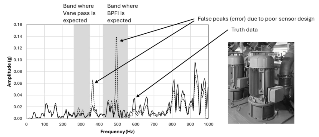
A skilled vibration analyst could determine if the peaks represent actual faults by evaluating if the fault frequency peaks move with machine speed. Real fault frequency peaks will move with speed whereas the sensor false peaks will not move because the natural frequency of the sensor for a given design and mount.
In any case, chasing down sensor error is time-consuming and not what a vibration analyst or maintenance technician wants to work on.
Because faults are relatively rare, and the fault frequencies must overlap with the region of error, most customers using unstable sensors will not know upfront that their assets are not being accurately monitored. However, over time and at scale, faults will be missed, and false positive diagnoses will begin to erode trust in the condition monitoring program. When choosing a vibration sensor, it is worth considering how well they are designed to ensure accurate diagnosis in all cases.
Conclusion
Peak error of common sensors in the predictive maintenance market are expected to fall between 60-410%. This magnitude of sensor error will lead to misdiagnosis and false positives. Because the error is only expressed in certain cases, it is difficult for reliability engineers to know when a fault is due to sensor error or an actual machine fault. Identifying and avoiding sensor problems–rather than focusing on machine problems–is costly and lowers the ROI for predictive maintenance solutions. This problem also highlights the fact that many sensors on the market would provide more accurate machine health assessment if they only used the vertical axis, essentially treating them as a single axis sensor. However, the diagnostic benefit of having both axial and radial measurements would be lost.
Unfortunately, because the predictive maintenance market has not yet matured, some companies misrepresent their products, likely not to intentionally mislead customers, but because they simply do not know or understand that their products are error prone. The Instability Index described in this paper helps end-users choose wireless sensor products that will provide reliable diagnostic readings. With innovation and intelligent design, high accuracy measurement (<6% error) can be achieved as is evident by the performance of KCF’s VSN3 product.
About
In 2000, KCF Technologies was founded to transform technology into real-world solutions that elevate people and industries. By 2006, KCF deployed one of the first wireless machine health monitoring solutions in an industrial application. From 2008 to 2014, KCF expanded across industries—wastewater facilities, pulp and paper mills, chemical plants, lumber mills, Navy helicopters and submarines—saving customers over 100,000 hours of downtime. With nearly 25 years of expertise and a commitment to innovation, KCF continues to deliver best-in-class predictive maintenance solutions to nearly 1,000 manufacturing locations.
